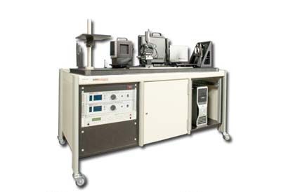
The RTB 3000 Detector Test Bench from Santa Barbara Infrared (SBIR) is a flexible integrated IR detector test station for evaluation of single element detectors, linear arrays, and focal plane arrays. The RTB 3000 provides the radiometric stimulus necessary to perform accurate IR detector testing in both laboratory and production environments.
The SBIR system is designed to be integrated with most data acquisition systems to perform the automated tests and analysis required for complete detector characterization. Alternately, the RTB 3000 can interface with the user’s own detector support electronics to perform detector testing and analysis.
The blackbody sources and optics of the RTB 3000 are designed to be quickly and accurately reconfigured for flood-mode, focused-mode and collimated-mode testing. Tests such as MTF, crosstalk, spot scan, and D* are easily performed with excellent accuracy and repeatability.
The RTB 3000 allows rapid set up and simple documentation of the test configuration, yielding accurate, consistent test results. This integrated approach removes many of the errors associated with set up and alignment of multiple test configurations.
Features
High Accuracy Testing
SBIR has taken a systems level approach and applied years of IR detector testing expertise in the development of the RTB 3000. State-of-the-art radiometric and optomechanical components give unmatched accuracy and test repeatability.
Easily Reconfigurable
The RTB 3000 achieves a high degree of versatility with a minimum number of components. To reconfigure the system, the user merely places sources and optical modules on the pre-aligned quick-change kinematic mounts, thus minimizing down time between tests. See various test setups below for more information.
Computer Interface
The RTB 3000 is provided with all necessary interfaces to communicate with a host computer featuring IRWindows™ Test Software. Automation in controlling all blackbody temperatures, target and filter selection, spot motion and focus, modulator status, and other parameters is possible via the supplied computer interfaces.
RTB 3000 Compatibility
The RTB 3000 is designed to easily integrate with most data acquisition systems such as Pulse Instruments’ systems. These systems supply the electrical interface to the unit under test (UUT), while the RTB 3000 supplies all necessary radiometric inputs. The powerful, easy-to-use, optional software packages for the RTB 3000 are menu driven and flexible. Hardware and software are modular and easily customized for specific UUTs or non-standard tests.
Dewar Compatibility
The optical system of the RTB 3000 can accommodate virtually all dewar assemblies. The standard bench configuration supports sidelooking dewars, and is easily modified to support downlooking dewars as well.
Focused Mode Tests:
In focused-mode tests, the RTB 3000 focuses energy from an infrared-illuminated aperture or target onto individual pixels of the detector. Typical focused-mode tests include crosstalk, spot scan and MTF. The optical system of the RTB 3000 allows focused-mode testing to be performed with either the high temperature cavity blackbody or the low temperature extended area source.
Crosstalk
Crosstalk is a measure of the signal from nearby pixels when one pixel is illuminated. By design, Modern FPAs have pixel sizes approaching the diffraction limit, placing strict requirements on the positioning system. The RTB 3000 provides a means for software control of X-Y-Z spot motion, allowing the user to readily find the optimum spot position.
Spot Scan
In spot scan testing, energy is focused onto and scanned across the focal plane array. Analysis of the detector output versus spot position provides a straightforward check for crosstalk and reflections from the edges of substrates or cold shields. Spot scans can also be done for large detector pixels to identify spatial non-uniformities. The RTB 3000 makes reproducible spot scan measurements quick and easy.
Modulation Transfer Function
The modulation transfer function (MTF) is easily measured using the RTB 3000. To measure MTF of a detector, a slit image is scanned across the detector, while the host computer records the output from one or more pixels.
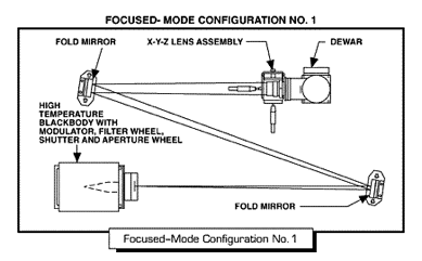
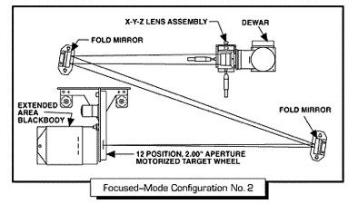
Flood Mode Tests:
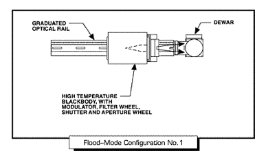
In flood-mode tests the RTB 3000 illuminates the detector with unfocused blackbody energy from either the extended area source or the high temperature cavity source. Flood-mode tests include responsivity, noise, uniformity, detectivity, and linearity. Source location is precisely established using the RTB 3000’s graduated optical rail and quick-change kinematic mounts, for accurate control of irradiance.
Responsivity
Responsivity is the change in electrical output per unit of radiometric input. To measure responsivity, an extended area blackbody is placed immediately in front of the detector array, or a high temperature cavity blackbody with the required aperture size is placed at a required distance from the detector. Responsivity is a critical measured value, as it is used to calculate D*, NEDT, NEI, and quantum efficiency. The flexible design of the RTB 3000 allows the test engineer to select the responsivity test configuration that best fits the preferred test philosophy.
Noise
The noise measurement test is another flood-mode test. The extended area blackbody source, set at or near ambient temperature, floods the detector. With a fixed input, the noise is the root-mean-square deviation of the electrical output over time. Noise is another critical measured value used to calculate D*, NEDT, and NEI. The state-of-the-art SBIR blackbody sources incorporated into the RTB 3000 allow stable and accurate noise measurements to be performed.
Uniformity
Uniformity is a measure of pixel-to-pixel variation in output of a focal plane array while it is flooded with constant, uniform irradiance. The extended area blackbody is positioned to fill the detector field of view, providing uniform infrared stimulus to the array. Data for each element of the array is collected, and standard deviation or other statistics are calculated.
Detectivity
Detectivity (D*) is a useful calculated figure of merit for comparing one detector to another. D* is the responsivity times the square root of the detector area divided by the noise spectral density. D* calculation is a standard feature of the RTB’s optional software packages. The D* figure is commonly reported with reference to a specific blackbody temperature. The RTB 3000’s blackbody sources supply all standard temperatures typically used for D* measurements.
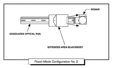
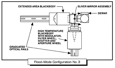
The RTB 3000 provides a new approach to testing linearity that avoids the limitations of the traditional approach. Rather than measuring the absolute value of the output voltage of the detector throughout its range, the slope of the V(Q) curve is measured at selected points. To do this, the detector is illuminated simultaneously by both the extended area source and by the modulated high temperature source. Varying the temperature of the extended area source allows the nominal irradiance to be set. The modulated high temperature source provides a precisely repeatable variation around this nominal value. The a.c. component of the detector output will be proportional to the detector responsivity. The slope of V(Q) is proportional to the resulting a.c. component of the detector output. Using this method, deviation from linearity can be determined with extremely high accuracy.
Collimated Mode Tests:
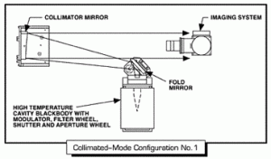
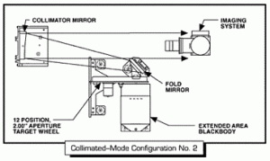
The tests describe previously are done on detectors or systems that do not form an image. The capability of the RTB 3000 is easily extended to allow testing of imaging systems: a collimating mirror is added, illuminating the imaging system with collimated energy from the differential blackbody source and target wheel or the cavity source and aperture wheel. This allows routine measurement of MTF, SiTF, NETD, and MRTD at the system level, and eliminates the need for a separate IR target projector system.
AUTO MRTD (Minimum Resolvable Temperature Difference)
AutoMRTD is calculated from the NETD and MTF multiplied by a response function, K(f):
AutoMRTD = K(f) x [NETD/MTF]
Where K(F) = ManMRTD/[NETD/MTF]
The K(f) values are determined from a statistical sample of ManMRTD measurements. The range of ManMRTD measurements taken depends on the specifics of the system under test. Ideally, several different trained operators take measurements several times a day for several days. The average of these measurements are used to calculate the K(f)’s. Since these values are derived from previous tests, no additional targets are needed.
SiTF (Signal Transfer Function)
SiTF is the slope of the output voltage vs. differential temperature curve. To measure SiTF, the UUT views the Half-Moon Target. The mean values are calculated from the ambient area and from the signal area. The voltage difference corresponding to the temperature difference is obtained. The differential temperature is then changed to obtain another data point. When a set of points (typically six) is obtained, the slope of a line tangent to the curve is computed. This slope is the SiTF. The SiTF is used in the NETD calculation.
MTF (Modulation Transfer Function)
MTF is calculated from an edge input, using the Half-Moon Target. The edge trace is differentiated to obtain the line-spread function, and a Fast Fourier Transform (FFT) is performed to obtain the frequency values.
This frequency output is normalized to get the 0 to 100% modulation values. The software will display a graph of modulation versus spatial frequency. MTF data is also used in the Auto MRT Module.
NETD (Noise Equivalent Temperature Difference)
NETD is found by measuring the zero-signal noise from a Square Target or an open aperture, and dividing by the SiTF. The NETD is used in the Auto MRTD calculation.
Standard System – The base system of the RTB 3000 IR Detector Test Bench is capable of performing all of the common focused and flood-mode tests necessary to characterize IR detectors, linear arrays, and focal plane arrays.
| COMPONENT | FEATURES |
| Optical Bench Assembly | 30″ x 60″, Quick-change kinematic mounts, fold mirrors, graduated optical rails. |
| High Temperature Blackbody | 50 – 1000ºC, 1″ aperture; microprocessor control; IEEE-488 Interface. |
| Chopper / Modulator | 1 – 1000 Hz standard; stop-open, stop-closed; IEEE-488 Interface. |
| Shutter | 2 position, IEEE-488 Interface. |
| Filter Wheel | 5 position, 1″ aperture; IEEE-488 Interface. Aperture sizes of .050″, .100″, .200″, .400″, and .600″ are standard. Other sizes are available. |
| Extended Area Blackbody | 4″ square aperture, 0ºC to 100ºC (-25ºC to +75ºC ΔT) standard; microprocessor control; IEEE-488 Interface. |
| Sliver Mirror | Flat micro mirror on movable stage assembly. |
| X-Y-Z Lens Stage | 1 inch travel, 3 axis; microprocessor control; IEEE-488 Interface; lens mount for standard focusing lens. |
| Focusing Lens | 100mm efl, f/3, 3-5 micron. And /or 100mm efl, f/2, 8-12 micron lens. |
| Optional Components – By incorporating optional components, the RTB can be expanded to support system level testing. |
|
| Target Wheel | 2″ aperture, 12 position; IEEE-488 Interface. Standard FLIR test targets available. |
| Collimator | 6″ diameter, 30″ efl off-axis parabolic primary mirror; plano fold mirror. |
| 6″ Extended Area Blackbody | The standard 4″ extended area blackbody can be replaced with a 6″ square aperture blackbody to support large aperture flood-mode testing. |

Reviews
There are no reviews yet.